


KELLY LUU
×
Our Task: Create a wirelessly controlled vehicle, from concept to "final" iteration, that will traverse an obstacle course of varied terrain, including a 4:1 incline slope, utilizing class knowledge of laser-cutting, 3D modeling, 3D printing, soldering, basic circuits, Arduino microcontrollers, sensors, and actuators.
Our Timeframe: 4 weeks to iteratively prototype and refine the chassis and wireless control code.
Our Concept: Vehicle with a bluetooth-controlled drive wheel and turning mechanism (servo-controlled rocking arm with silicone stoppers on each end to create drag).
Result: Fastest vehicle to traverse the end of term obstacle course, passing two other vehicles en route.
Initial Sketch and Lo-Fi Cardboard Prototype

Watch Stopping Rover’s Journey in Action!
Med-Fi Iteration
This first med-fi prototype was solely intended to give us a better grasp on the vehicles physical layout and potential of our unique turning mechanism (can the stoppers generate enough drag to turn our vehicle?). Weight played a key role in our design, so it made sense to use sturdy material (laser-cut plywood) rather than cardboard in this stage of our design process.
There was a slight weight imbalance on the prototype due to the weight and off-setting position of the motor. Additionally, the stopper on the right end of the rocker arm frequently caught on the motor and didn’t reach the floor, creating a turning issue on our manual test run. Increasing the rocker arm length would resolve this. On the other end, the left stopper was functional and gave us slight proof of concept (PoC).
Med-Fi Iteration 2
WE HAD MOVEMENT AND IN MULTIPLE DIRECTIONS! This iteration gave us proof of concept! Extending the length of the rocking arm and coding the servo allowed us to run successful pre-bluetooth and post-bluetooth enabled tests.
We were still working on the weight imbalance, adjusting the position of materials and adding various counterweights to troubleshoot, eventually reorienting the drive wheel side as the back of the vehicle. Additionally, while we had PoC, turning wasn't the best because the stoppers had excessive play and the rocking arm kept bottoming out, limiting surface area contact for drag, so we needed to reduce stopper play and adjust the chassis to allow more clearance for the stoppers.
At this point, we needed to consider redesigning the chassis and address cable management.
Med-Fi Iteration 3
We lengthened the front of the chassis for stability, added deeper slots for arm clearance, added a separate power source to the servo (1x 4 AA battery set; other 2 sets power the drive wheel), and improved cable management.
At this point, we were still dealing with a weight imbalance, especially when we test ran on the ground and going up a 4:1 incline. It would not travel straight, instead choosing to veer and wheelie/flip over. During this same test, we also found the durability of the ping pong balls to be lacking. (Drive wheel and 2-wheel support model prior to 4-wheel support testing not pictured).
Knowing this, we tested the stability/durability of a 4-wheel support, first with 2 ping-pong balls and 2 soldering wire containers, eventually opting for a 4-wheel support redesigned chassis using all 4 of the latter, focused on even weight distribution.
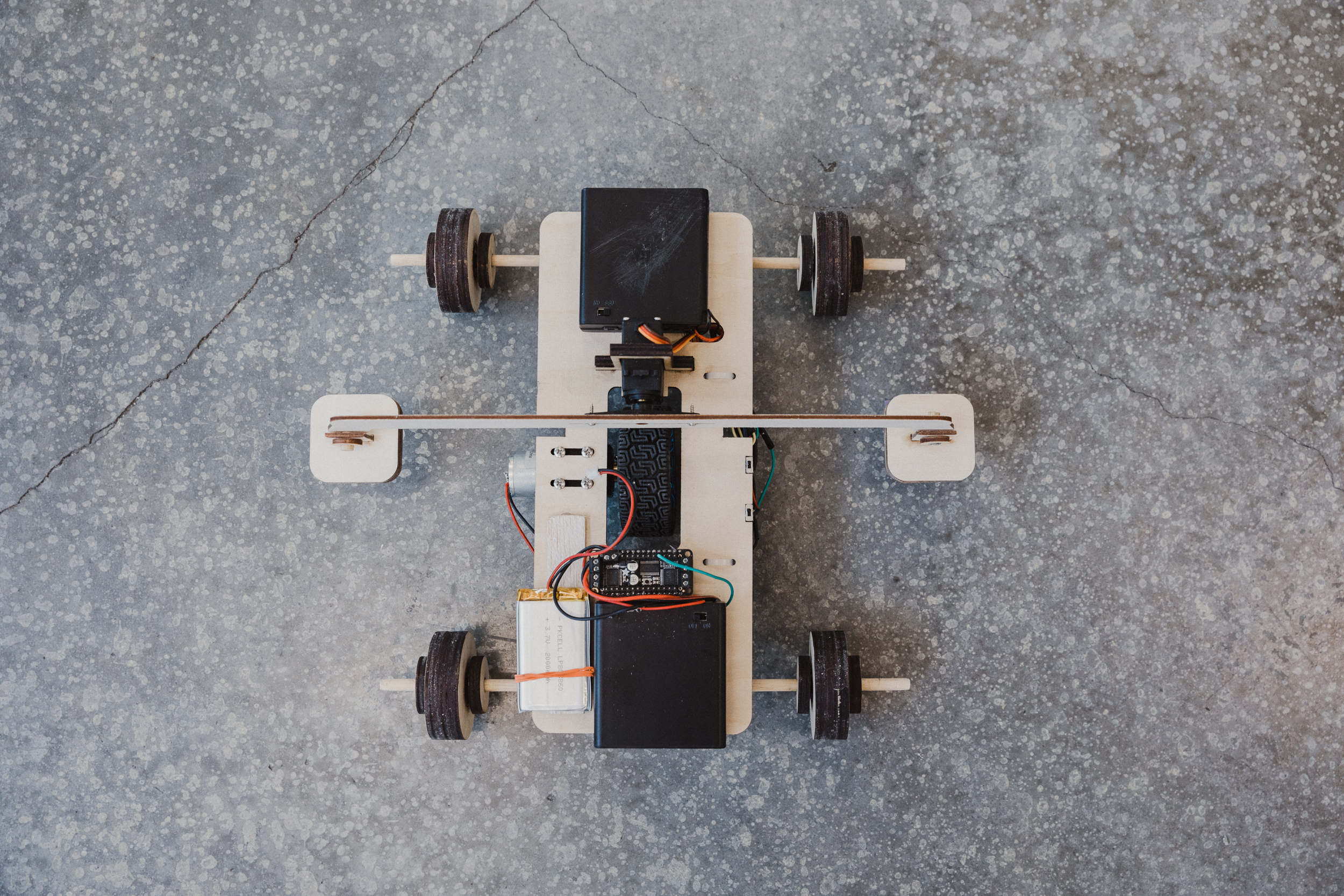
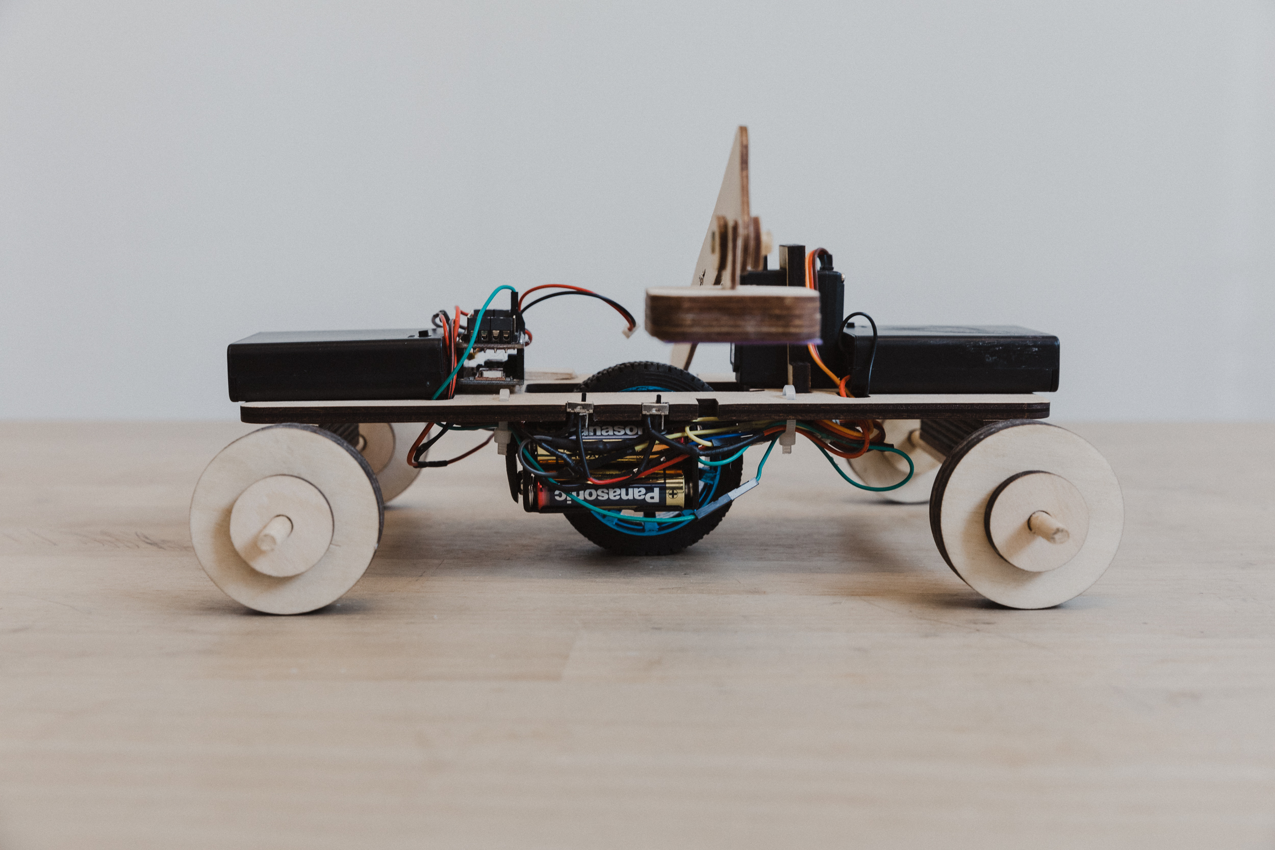
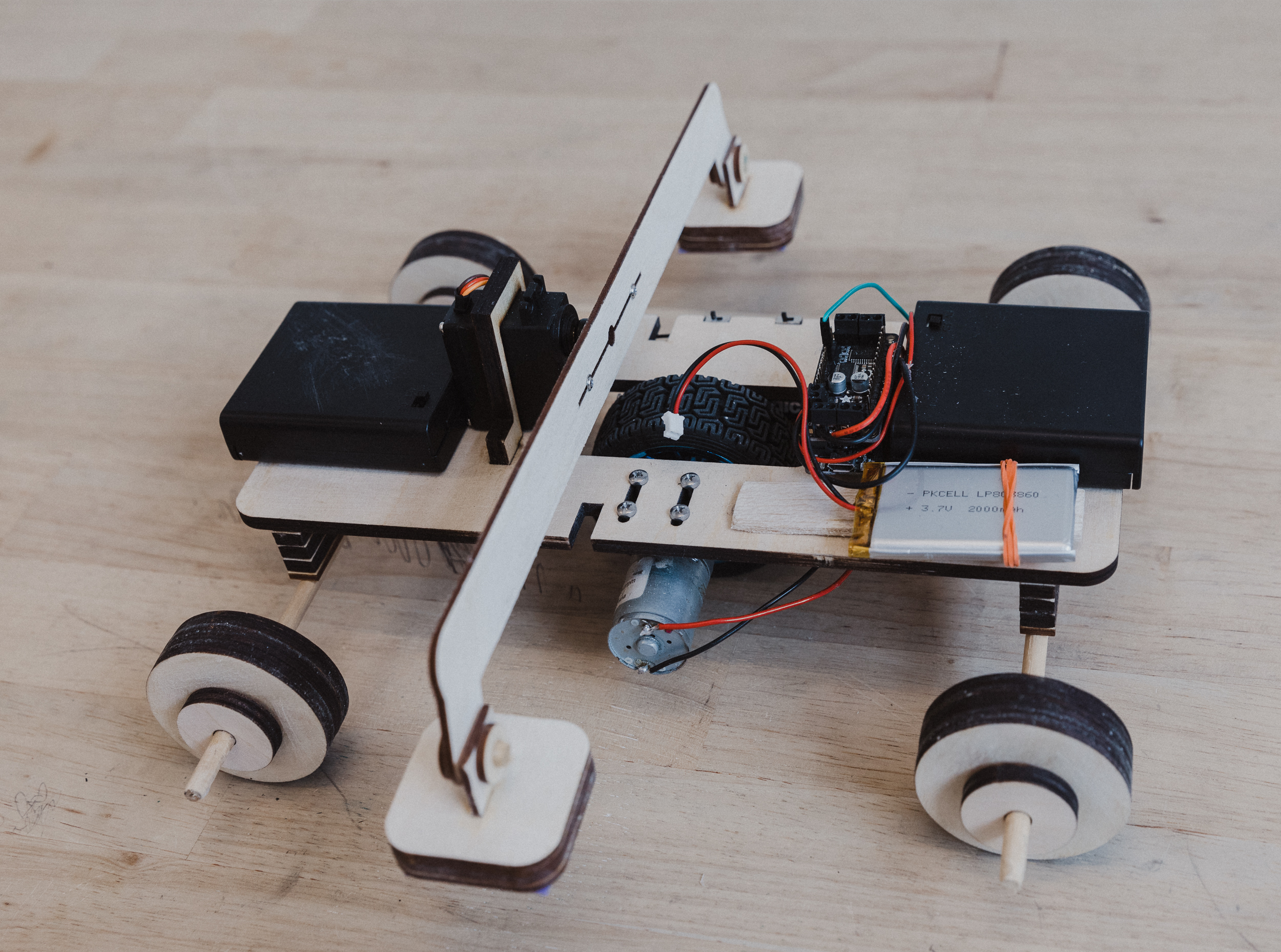
Final Prototype
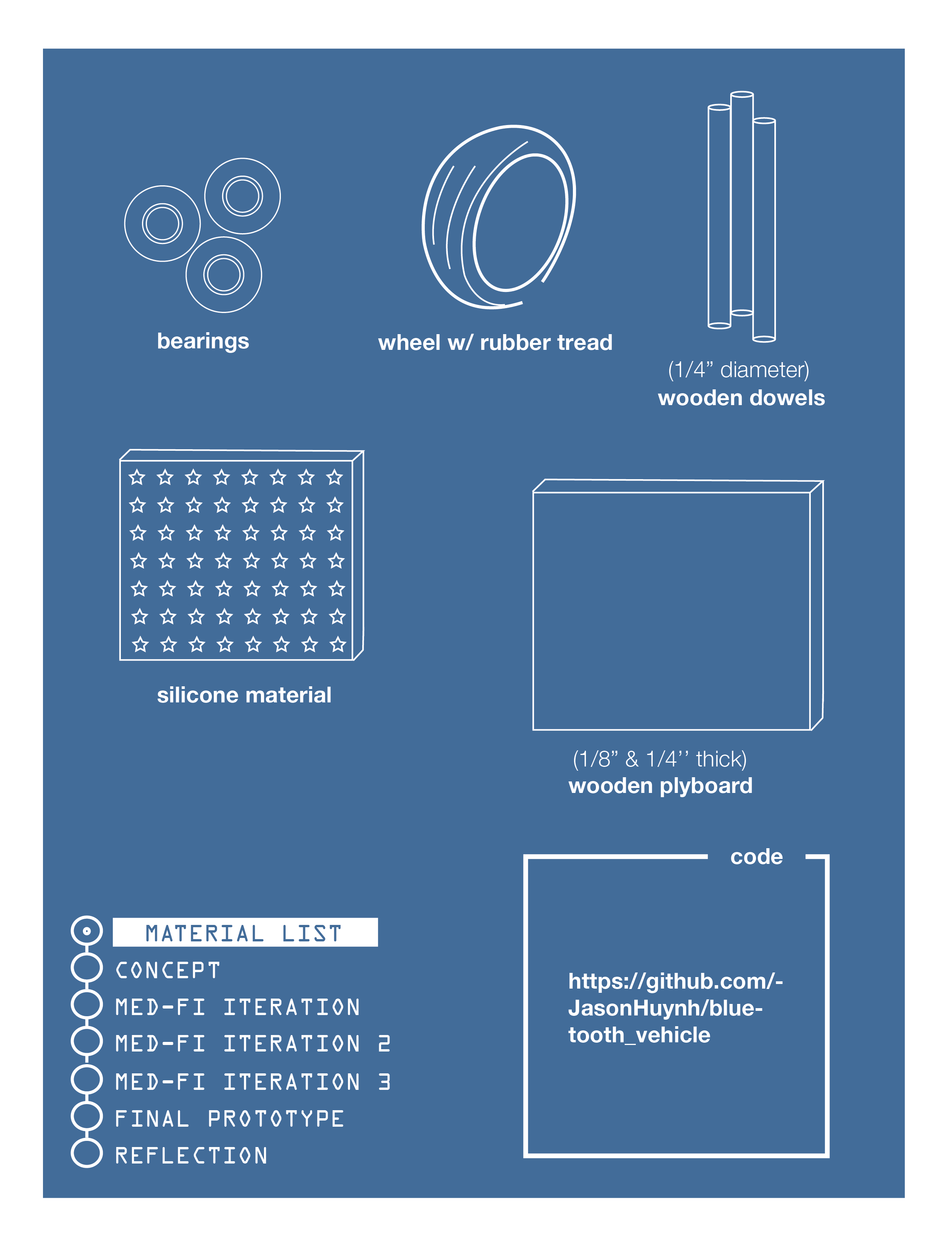
In this final iteration, we used a 1/4” thick, rectangular chassis instead of a 1/8” thick, “T” chassis, for better stability and weight distribution. We opted for laser-cut plywood wheels as not only an aesthetic decision over the soldering wire containers, but also a durability decision over the ping pong balls, also opting to add bearings. We reduced the horizontal and vertical play on the stoppers to get the maximum amount of surface area contact for maximum drag. We also added better-positioned slots for cable management below the chassis, a housing support to keep the servo in place, and slots to flushly add power switches. For the bluetooth controller, we added two speed modes for flexibility when maneuvering through different obstacles (i.e. slalum vs. incline).
Reflection: When we first began designing our bluetooth-controlled vehicle, we knew we wanted to have a novel turning mechanism similar to rubber stoppers on the bottoms of canes/walkers. During the prototyping process, weight distribution was our main issue. Through rapid prototyping, we were able to troubleshoot and appropriately resdesign our chassis, wheels, and arms.
Overall, we were satisfied with our final product. It was simple, yet showed flexibility in maneuverability. In a future iteration, we would use a more secure and durable mounting system for the wheels, add a lightweight shell to cover exposed wiring, and create our own bluetooth controller rather than utilizing a smartphone.